
Forum Deutscheluftwaffe
Willkommen auf unserem Forum - Bordausrüstungen der Deutschen Flugzeuge zwischen 1914-1945 -- Das Forum zum Wissensaustausch für Flugzeugliebhaber und Freunde der deutschen Luftfahrt.HE 162 Panel CAD drawing
![]() #1 von
Manukun
, 24.12.2010 15:07
#1 von
Manukun
, 24.12.2010 15:07
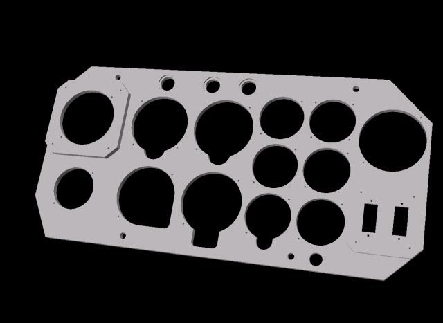
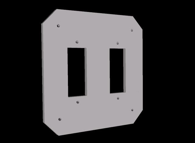
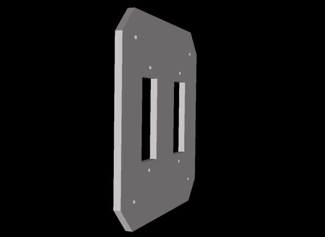
Hi All , I'm new on this forum and I will need some help to finish my CAD drawing.
I m working with the help of an original drawing coming from www.cockpitinstrumente.de but some informations are missing to finalize the drawing : 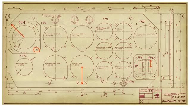
- the distance from the center of the plate to the holes for the FI 22412 is missing.
- the distance from the center of the plate to the bottom of the Kompass is missing.
- and the distance to drill the holes of the Schauzeichen is missing too.
here is a sample of my work ( please don't pay attention of the bad kompass shape).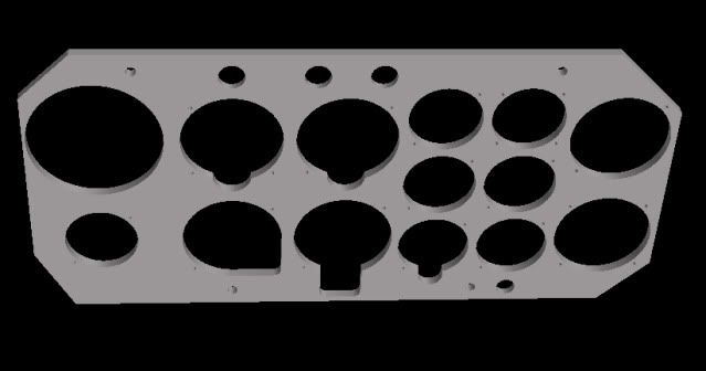
Thank a lot for your help.
Best regards
Manu
PS : I don't speak german so maybe I missed the "presentation section"
- Manukun

-
Beiträge: 6 Punkte: 6 Registriert am: 24.12.2010

RE: HE 162 Panel CAD drawing
![]() #2 von
Admin
, 24.12.2010 16:41
#2 von
Admin
, 24.12.2010 16:41
Hello
the "distance from the center of the plate to the holes for the FI 22412" is 60 mm (or together from screw hole to screw hole is 120 mm) as you can see in the pictures below ! But is not the distance for the Fl 22412 only for the plate to fix!
The distance for the Fl 22412 is 89 mm between the screw holes !
best regards
Admin
Erwin
- Angefügte Bilder:
- Aufgrund eingeschränkter Benutzerrechte werden nur die Namen der Dateianhänge angezeigt Jetzt anmelden!
-
Fl22407.jpg
Fl22427.jpg
- Admin

-
Beiträge: 173 Punkte: 173 Registriert am: 18.01.2010
RE: HE 162 Panel CAD drawing
![]() #3 von
Manukun
, 24.12.2010 18:02
#3 von
Manukun
, 24.12.2010 18:02
Hi Erwin,
thanks for your help.
The pictures you added are not for the FI 22412, is it normal ?
An additional quextion: was the panel made in plywood ?
Manu
- Manukun
-
Beiträge: 6 Punkte: 6 Registriert am: 24.12.2010
RE: HE 162 Panel CAD drawing
![]() #4 von
Viceroy
, 24.12.2010 18:22
#4 von
Viceroy
, 24.12.2010 18:22
Yes it is made from plywood, material either birch or beech
Since in the original RLM for the 22412 no distance for the holes are given, he added just a gauge with the same diameter.
the distance from the center of the plate to the bottom of the kompass is 58mm
the distance of the holes of the Schauzeichen is 42mm
Tomt of the forum just finished a superb CAD-drawing for the He162-board, shown here Unterschiedliche Gerätebretter (Fw190, Ta 152,...)
- Viceroy
-
Beiträge: 142 Punkte: 142 Registriert am: 19.10.2010
RE: HE 162 Panel CAD drawing
![]() #5 von
Manukun
, 24.12.2010 23:12
#5 von
Manukun
, 24.12.2010 23:12
Thanks Viceroy for the infos and the link to Tomt' drawing.
Merry Xmas.
Manu
- Manukun
-
Beiträge: 6 Punkte: 6 Registriert am: 24.12.2010
RE: HE 162 Panel CAD drawing
![]() #6 von
rookie1
, 25.12.2010 11:22
#6 von
rookie1
, 25.12.2010 11:22
Hello,
I would also say, the best way for you is to contact tomt. He did all the work already.
Just had a glance over your drawing:
Be aware that the mill outs of the indicators and the lamp in your drawing is not correct. Watch the drawing carefully.
Mill outs for the drehschauzeichen on top are from front, that one for the indicator lamp on bottom is from rear!
Be also aware, that the thickness of the two adaptor plates are not correct in the base drawing.
Correct is 8mm for the wendezeiger and 3mm for the indicators.
regards,
Harald
- rookie1
-
Beiträge: 223 Punkte: 223 Registriert am: 19.01.2010
RE: HE 162 Panel CAD drawing
![]() #7 von
Tomt
, 25.12.2010 14:26
#7 von
Tomt
, 25.12.2010 14:26
Mine is already finished. But with my programm and my knowledge I can not make such a nice 3D.
Be careful the holes are 2mm and not 3mm!
- Tomt

-
Beiträge: 50 Punkte: 50 Registriert am: 07.11.2010

RE: HE 162 Panel CAD drawing
![]() #8 von
Admin
, 25.12.2010 16:26
#8 von
Admin
, 25.12.2010 16:26
Hallo to all
I see that every year al people ask for the same questions about CAD programs and problems with there writtings.
Why people - dont put all there CAD files for everyone to the homepage for download - this is the reason why we got this hompepage - for everyone!
Make it eayser for all to rebuild one.
Like I did in the CAD section of the archive - I but my CAD data from the ME 163 for everyone online. And I will do also soon with my Ho 229 CAD data as well !
best regards and think about it...
Admin
Erwin
- Admin
-
Beiträge: 173 Punkte: 173 Registriert am: 18.01.2010
RE: HE 162 Panel CAD drawing
![]() #9 von
Manukun
, 26.12.2010 16:35
#9 von
Manukun
, 26.12.2010 16:35
Thanks to all,
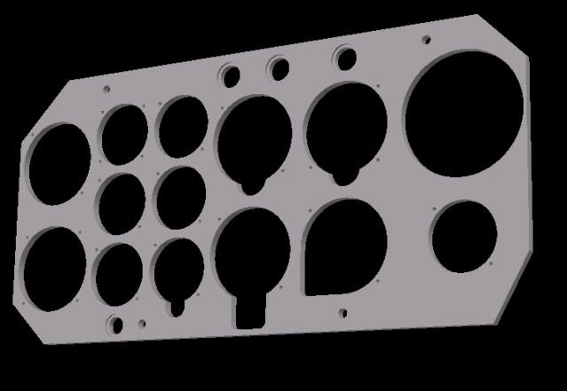
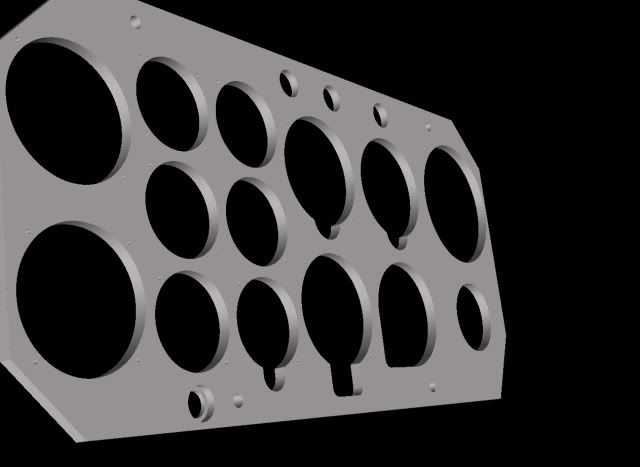
I modified the drawing according to all the informations you gave to me.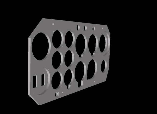
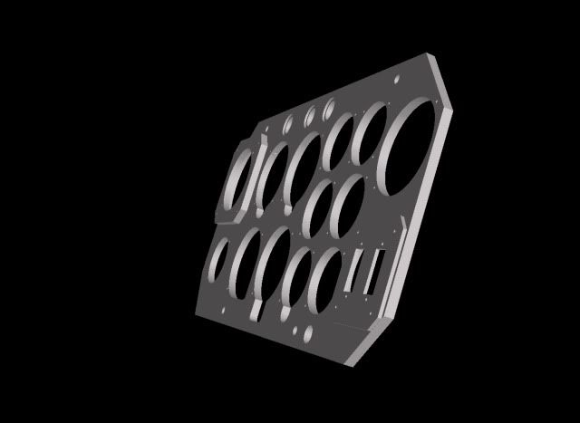
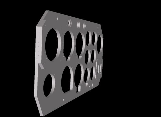
Please let me know if some other modifications are necessary.
Erwin, can you please give me the link to post the CAD drawing in the correct section (I don't speak german and can't find the section).
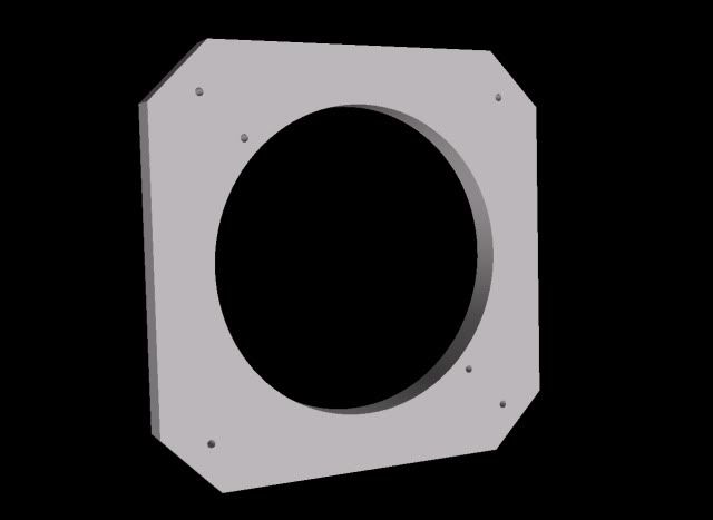
By the way does any one have the specification to draw the 1M4 'hole cover plate" ?
Thanks.
Manu
- Manukun
-
Beiträge: 6 Punkte: 6 Registriert am: 24.12.2010
RE: HE 162 Panel CAD drawing
![]() #10 von
rookie1
, 26.12.2010 17:21
#10 von
rookie1
, 26.12.2010 17:21
Hello,
looks good. Anyhow, the depth ofthe mill outs look not very deep. The depth should be 5mm. So the remaining thickness is 3mm only. Especially for the indicator lamp this is necessary because the max thickness it can cover is 3mm.
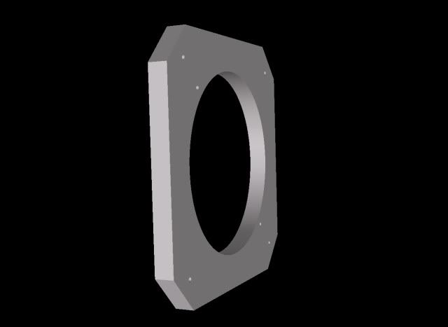
The blind plate was normally made of 1mm aluminium. Measurement is approx. 62 to 63 mm square with rounded edges of approx. r5.
Regards,
Harald
- rookie1
-
Beiträge: 223 Punkte: 223 Registriert am: 19.01.2010
RE: HE 162 Panel CAD drawing
![]() #11 von
Manukun
, 26.12.2010 18:14
#11 von
Manukun
, 26.12.2010 18:14
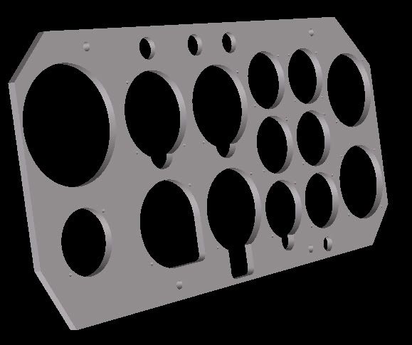
Hi Harald you re right : it was not deep enought !
modifications done + the blind plate : 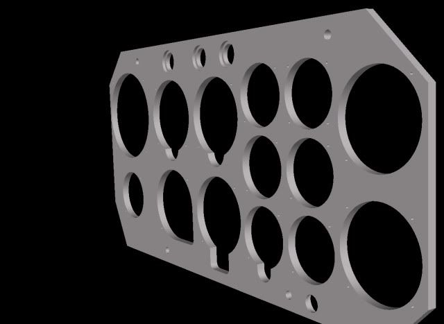
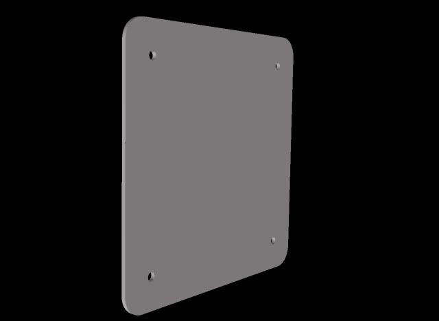
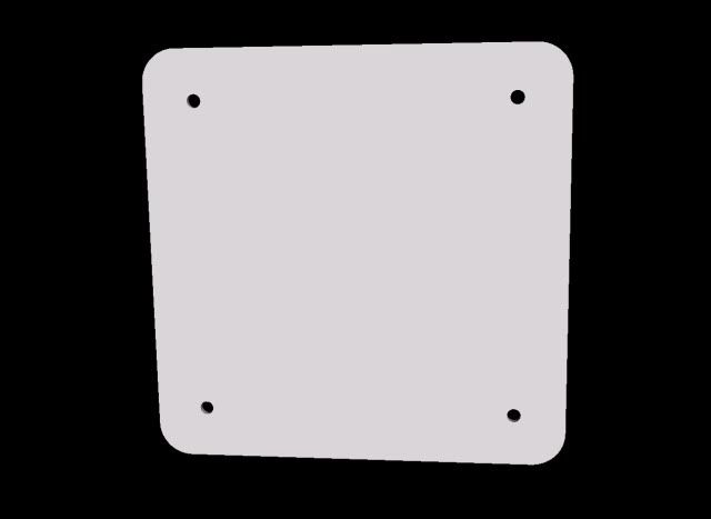
Thanks.
Manu
- Manukun
-
Beiträge: 6 Punkte: 6 Registriert am: 24.12.2010
RE: HE 162 Panel CAD drawing
![]() #12 von
rookie1
, 26.12.2010 21:58
#12 von
rookie1
, 26.12.2010 21:58
Hello,
I looked in the original spare parts list. Here it is said, the blind plate shall be made of 3mm plywood with the dimensions 62x62.
Anyhow, in the original photos I know, the plate is much thinner. Therefore I believe it was made from 1mm aluminium most of the time, like it was usual for other aircraft also. 62x62 might be the right dimension.
Have you also checked the mill outs for the upper holes? Along the drawing they are 3mm, which seems to be ok. The nut of the drehschauzeichen is 3.5mm high, this means they look 0.5mm out of the hole. This is like it looks in the original photos also.
Regards,
Harald
- rookie1
-
Beiträge: 223 Punkte: 223 Registriert am: 19.01.2010
RE: HE 162 Panel CAD drawing
![]() #13 von
Manukun
, 27.12.2010 11:38
#13 von
Manukun
, 27.12.2010 11:38
Thanks Harald,
I m working again on the plate and I will post new pictures later.
Regards
Manu
- Manukun
-
Beiträge: 6 Punkte: 6 Registriert am: 24.12.2010
